-
NSX OSPF configuration – Creating Networks
We first need to setup the environment before we can do the OSPF configuration. To do that we need to create a few Logical Switches (LSw) within the NSX UI.
Task ID
Task Description
Screenshot
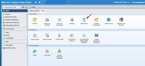
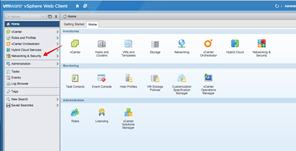
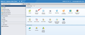
In the Web Client, Click on the Networking Icon?
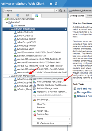
Right click on the Distributed vSwitch that is hosting the networks connected to the Internet/production networks.
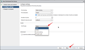
Select New Distribution Group.
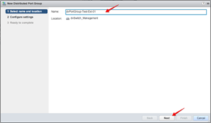
Type a new name in the Name field.
We are using dvPortGroup-Test-Ext-01.
Click Next.
Leave most settings as per default, and only change the VLAN Type to what is required.
Here select None as we do not have VLans configured.
Click Next.
Review the summary and click Finnish.

The new dvPortGroup is shown.

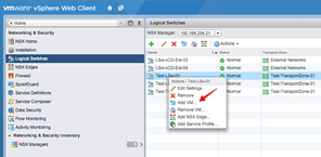
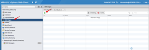
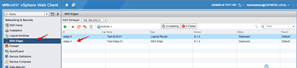
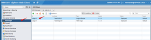
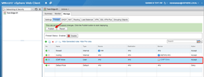
Click Home, then click Networking & Security in the Left menu.
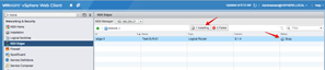
Click Logical Switches, to show the current configuration.
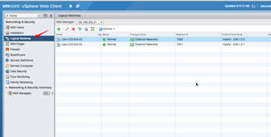
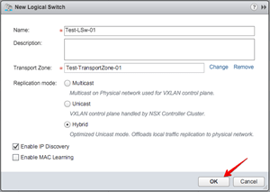
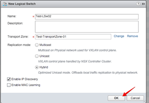
Three Logical Switches needs to be created. Click on the Green + sign to add a new Logical Switch.

Complete the Name field:
Test-LSw-01
Click on the Change button to Select the Transport Zone:
Test-TransportZone-01
Leave the other option as default and click OK.
Click on the Green + sign to add a new Logical Switch.
Complete the Name field:
Test-LSw-02
Click on the Change button to Select the Transport Zone:
Test-TransportZone-01
Leave the other option as default and click OK.
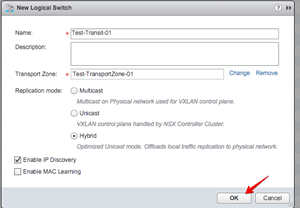
Click on the Green + sign to add a new Logical Switch.
Complete the Name field:
Test-Transit-01
Click on the Change button to Select the Transport Zone:
Test-TransportZone-01
Leave the other option as default and click OK.
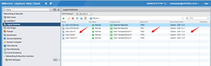
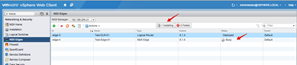
The three Logical Switches are shown.
With their Segement ID’s and the Control Plane modes.
-
NSX OSPF configuration – Adding Virtual Machines to Logical Switches
Now that the have the Logical Switches (LSw) created, we need to connect our test VM’s to those switches. We can use the NSX UI for that too.
Task ID
Task Description
Screenshot
Right Click the First Logical Switch:
Test-LSw-01
From the menu, select Add VM…
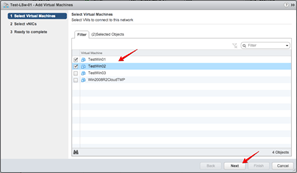
Select the two TestVM’s we will be using for Logical Switch:
Test-LSw-01
Click Next.
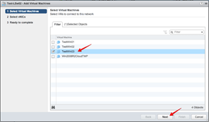
Select the vmnic’s to be used for each TestVM.
TestWin01
TestWin02
Click Next.

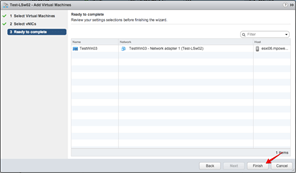
Review the Summary, and Click Finnish.

Right Click the Second Logical Switch:
Test-LSw-02
From the menu, select Add VM…

Select the third TestVM’s we will be using for Logical Switch:
Test-Win03
Click Next.
Select the vmnic’s to be used for each TestVM.
Click Next.

Review the Summary, and Click Finnish..
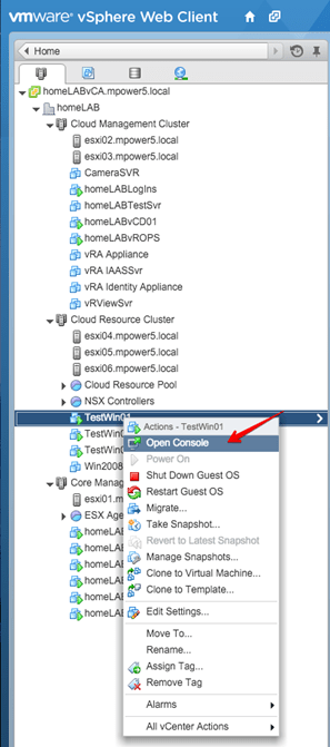
Click on Home, then click Host and Clusters.
Expand the selections, Right Click the first TestWin01 VM.
Select Open Console.
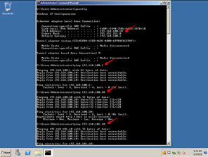
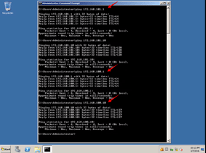
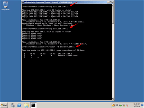
From the Console window, log into the VM, opena Command window.
Ping its own IP address, 192.168.100.10 – this should work
Ping the Router address, 192.168.100.1 – This should fail as we have not setup the Distributed Logical Router (DLR)
Ping it adjasent TestWin02, 192.168.100.20 – this should work
From the Console window, log into the VM, opena Command window.
Ping its own IP address, 192.168.100.20 – this should work
Ping the Router address, 192.168.100.1 – This should fail as we have not setup the Distributed Logical Router (DLR)
Ping it adjasent TestWin01, 192.168.100.10 – this should work
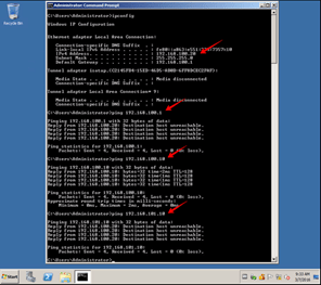
From the Console window, log into the VM, opena Command window.
Ping its own IP address, 192.168.101.10 – this should work
Ping the Router address, 192.168.101.1 – This should fail as we have not setup the Distributed Logical Router (DLR)
Ping it remote TestWin01, 192.168.100.10 – This should fail as we have not setup the Distributed Logical Router (DLR)
-
NSX OSPF configuration – Adding the Logical Distributed Router
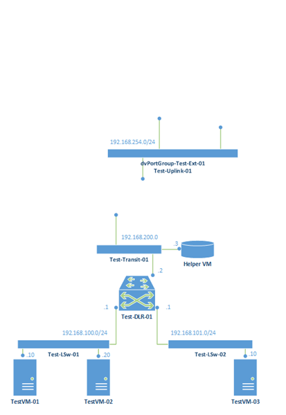
We have added the Logical Switches, VM’s and done basic ping tests. We create a Distributed Logical Router (DLS) to connect the two Logical Switches (LSw)
Task ID
Task Description
Screenshot
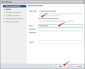
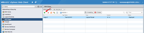
Click on the NSX Edges, left menu, and click the Green + to add a new Distributed Logical Router
Select Logical Distributed Router.
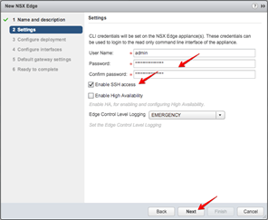
Type a Name in the fiel:
Test-DLR-01
Click Next.
Type a complex Password, confirm the password.
Select the Enable SSH access tick box. We are doing this so that we can access the Router interface for testing.
Note: Depending on your policies, you may not want this enabled in a production envrionment
Click Next.
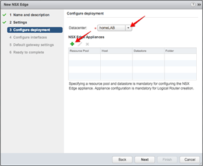
The default Datacenter should be listed.
Click the Green + sign to add a NSX Edge helper VM.
Note: This VM is created to manage the Distributed Logical Router (DLR) ARP tables, and configuration.
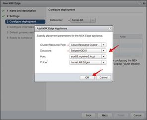
Select the Cluster/Resource Pool:
Cloud Resource Pool
This is the Cluster the NSX Controllers are in.
Select Datastore:
StripedHDD01
Either a dedicated datastore for edges or a random accessable datastore.
Select Host:
Esxi06.mpower5.local
Can be any of the host in the cluster
Select Folder:
homeLAB Edges
A Folder to hold all our Edge devices.
Click OK.
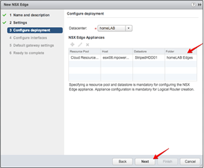
The Edge configuration is shown.
Click Next.
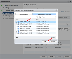
Click on the Select button.
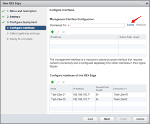
From the Distributed Portgoup section select the dvPortGroup we created in the beginning:
dvPortGroup-Test-Ext-01
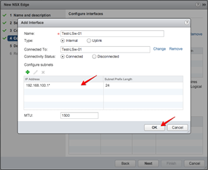
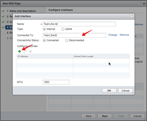
Click the Green + under the Configure Interfaces for this NSX Edge.
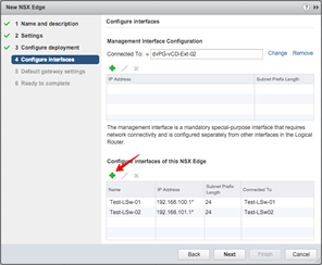
Type a Name for the Interface, we keep it the same as the LSw it connects to:
Test-LSw-01
Select Internal. This is because the network will be internal (private) to the device.
Click Change, and Select the Logical Switch:
Test-LSw-01
Click the Green + sign to add the subnet.
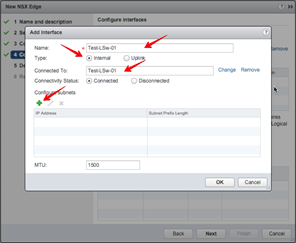
Click the Green + sign to add the IP address:
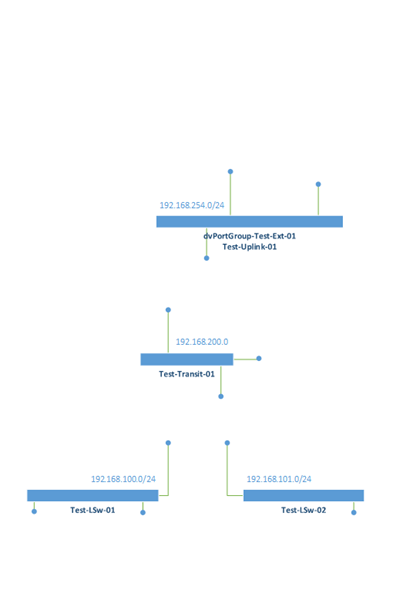
192.168.100.1
Subnet prefix lenth:
24
Click OK.

The configuration is shown.
Click OK.
Click the Green + under the Configure Interfaces for this NSX Edge.
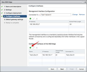
Type a Name for the Interface, we keep it the same as the LSw it connects to:
Test-LSw-02
Select Internal. This is because the network will be internal (private) to the device.
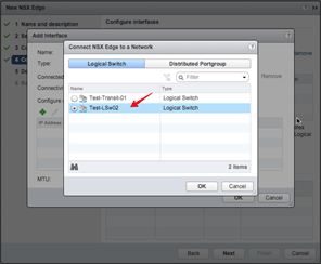
Click Select, and Select the Logical Switch:
Test-LSw-02
Click the Green + sign to add the subnet.
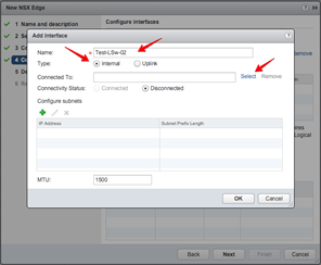
Click Select, and Select the Logical Switch:
Test-LSw-02
Click OK.
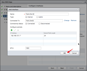
Click the Green + sign to configure subnets.
Click the Green + sign to add the IP address:
192.168.101.1
Subnet prefix lenth:
24
Click OK.

The Configuration is shown.
Click OK.
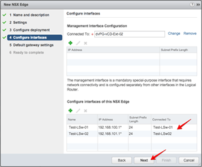
The summary is shown.
Click Next.
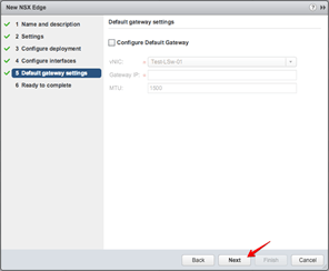
From the Default gateway settings, de-select the box next to:
Configure Default Gateway.

Click Next.
Review the summary, click Finnish.

The Helper VM (Edge) is deployed and configured.
The Helper VM (Edge) is deployed and configured.

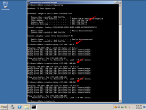
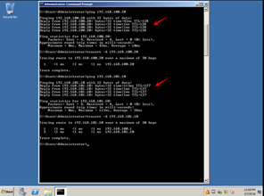
To test the configuration, Open the TestWin01 Console.
Ping its own IP address, 192.168.100.10 – this should work
Ping the Router address, 192.168.100.1 – This should now work as we have setup the Distributed Logical Router (DLR)
Ping it remote TestWin01, 192.168.101.1 – This should now work as we have setup the Distributed Logical Router (DLR)
Ping the remote TestWin03 address, 192.168.101.10 – This should now work as we have setup the Distributed Logical Router (DLR)

To test the configuration, Open the TestWin01 Console.
Ping its own IP address, 192.168.101.10 – this should work
Ping the Router address, 192.168.101.1 – This should now work as we have setup the Distributed Logical Router (DLR)
Ping it remote TestWin01, 192.168.100.1 – This should now work as we have setup the Distributed Logical Router (DLR)
Ping the remote TestWin03 address, 192.168.100.10 – This should now work as we have setup the Distributed Logical Router (DLR)
-
NSX OSPF configuration – Adding the Edge Router
Next we add the Edge Router to the environment. The edge Router will be connecting our VM’s to the internet.
Task ID
Task Description
Screenshot
At the NSX Edges Left Menu, Click on the Green + sign to add another NSX Edge.
Select Edge Services Gateway.
Type a Name in the Field:
Test-Edge-01
Click Next.

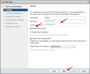
Type an admin Password and confirm the Password.
Select the tick box next to Enable SSH Access.
This is so we can login to the Router console to do testing.
Note: Depending on your policies, this might not be required for Production use.
Leave the Enable auto rule generation ticked.
Click Next.
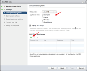
The default Datacenter should be listed.
Leave the Appliance size at Compact.
Note: The size of the appliance determines it speed and scale.
Leave the Deploy NSX Edge tiked.
Click on the Green + sign to add a NSX Edge device.
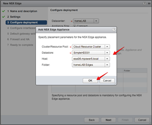
Select the Cluster/Resource Pool:
Cloud Resource Pool
This is the Cluster the NSX Controllers are in.
Select Datastore:
StripedHDD01
Either a dedicated datastore for edges or a random accessable datastore.
Select Host:
Esxi06.mpower5.local
Can be any of the host in the cluster
Select Folder:
homeLAB Edges
A Folder to hold all our Edge devices.
Click OK.
Click Next.
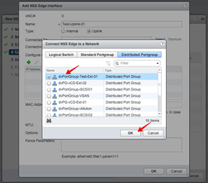
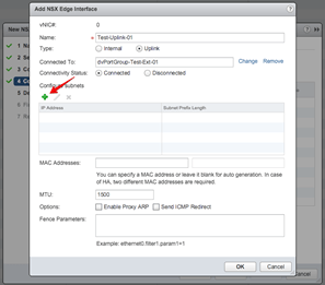
Click the Green + sign to add the following interfaces:
Uplink and Transit.

Type a name in the Name field:
Test-Uplink-01
Select Uplink.
Click on the Change button to select the Connected To:
dvPortGroup-Test-Ext-01

Click on the Change button to select the Connected To:
dvPortGroup-Test-Ext-01
Click OK.
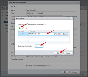
Click the Green + sign to add the subnet.
Click the Green + sign to add the IP address of the Uplink interface:
192.168.254.250
Note: This IP address will be on the External (Internet) network
Click OK.
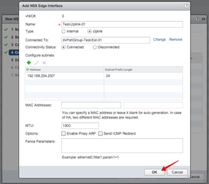
Review the changes and Click OK.
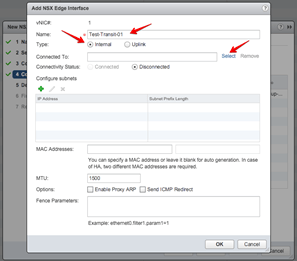
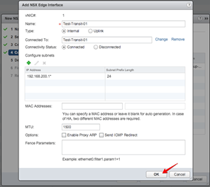
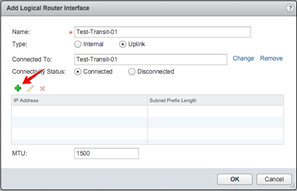
Click the Green + sign to add the following interfaces:
Transit.
Type a name in the Name field:
Test-Transit-01
Select Internal.
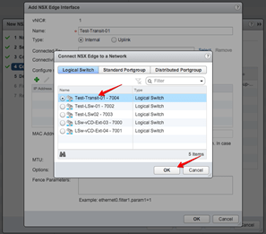
Click on the Select button to select the Connected To:
Test-Transit-01
Click on the Change button to select the Connected To:
Test-Transit-01
Click OK.
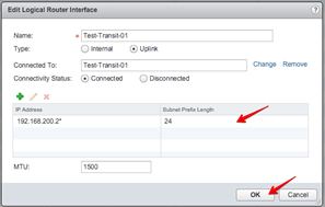
Click the Green +
sign to add the subnet.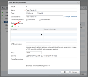
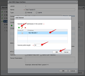
Click the Green +
sign to add the IP Address of the inside of the NSX Edge on the Transit network:
192.168.200.1
Click OK.
Review the changes and Click OK.
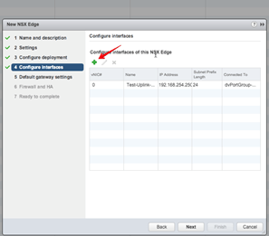
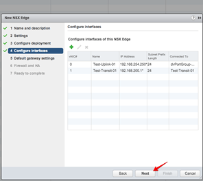
Review the interface configuration, and Click Next.
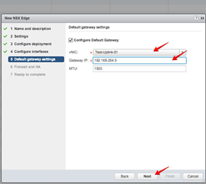
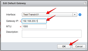
Configure the Default gateway settings:
vNIC: Test-Uplink-01
Gateway IP: 192.168.254.5
Note: This is the Router IP on the External (Internet) network.
Click Next.
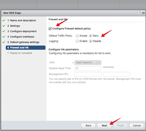
Click the Tick box next to Configure Firewall default policy
Select Default Traffic Policy: Deny
Leave other options at default.
Click Next.

Review the summary and click Finnish.
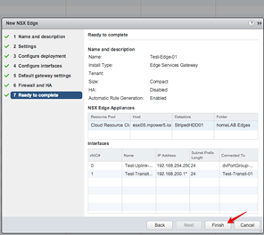
A new NSX Edge is deployed and configured.
A new NSX Edge is deployed and configured.
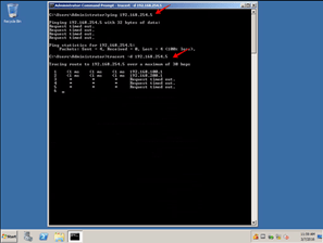
Testing form TestWin01:
Ping the Router IP address,
192.168.100.1 – This will work as we are still connected to the Distributed Logical Router (DLR)
Ping the Edge Gateway IP address, 192.168.200.1 – Thi will fail as we have not yet setup OSPF.
Log into the NSX DLR:
Test-DLR-01
Console.
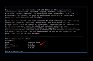
Username: admin
Password: <Password>

Enter at the prompt:
Show ip route
The DLR route table is shown.
The DLR is connected to both the following Logical Switches:
Test-LSw-01
Test-LSw-02
Log into the NSX Edge:
Test-Edge-01
Console.
Username: admin
Password: <Password>
Enter at the prompt:
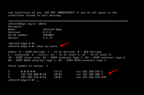
Show ip route
The Edge route table is shown.
The Edge is connected to:
Default route: 0.0.0.0/0
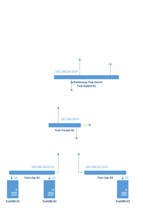
Transit Network: 192.168.200/24
External Network: 192.168.254/24
Ping the default External Router IP address, 192.168.254.5 – This should work showing connectivity to the External Network.

-
NSX OSPF configuration – Connecting the Edge to the Internet
We have connected all our components but due to OSPF not being setup, routes are not populated and thus no communication is working.

Task ID
Task Description
Screenshot
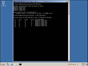
From the TestWin01 ping the default External Router IP address, 192.168.254.5 – This will not work showing that OSPF and Dynamic routes to the External Network is not funtioning.
-
NSX OSPF configuration – OSPF solution
Time to setup OSPF on our Edge Router, then our Distributed Logical Router (DLR) and test.

Task ID
Task Description
Screenshot
Select NSX Edge on the Left menu.
Double Click the NSX Edge Gateway:
Test-Edge-01.
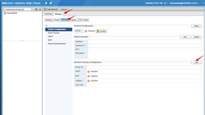
Click on Manage, then Routing and then OSPF.
Click on the Edit Button.
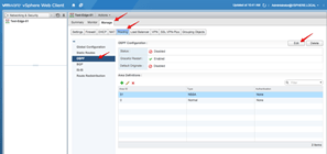
Click on the tick box to Enable OSPF.
Leave Enable Graceful Restart enabled.
We will NOT Enable Default Originate (for testing pusposes).
Note: If you enable Default Originate, the Edge Gateways default route will be advertised.
Click OK.

Click on Publish Changes to ensure your changes has been applied.
However, you may get this error..

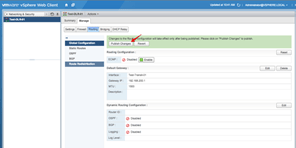
Click on Routing, Global Configuration.
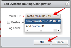
Click on Edit in the Dynamic Routing Configuration.
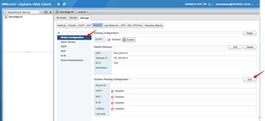
Select the Uplink:
Test-Uplink-01 – 192.168.254.250
as the Router ID.
Click OK.
Note: The Router ID must be unique in the OSPF tables. If not, errors might occur with dynamic route updates etc.

Click Publish Changes

Go back to Task ID 2 and complete the Enable OSPF.
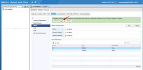
To enable OSPF on the DLR, we need to setup Area Definitions for the Peering between the DLR and the Edge.
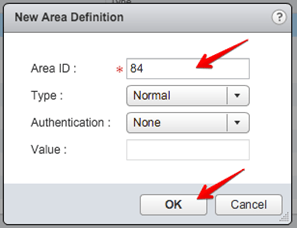
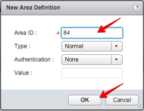
Click the Green + sign in the Area Definitions

Type Area ID:
84
Leave the defaults and Click OK.
Note: You can type any number as Area ID. We just selected 84.
Area ID : 0 is reseved
Area ID : 51 is reserved
Click Publish Changes.
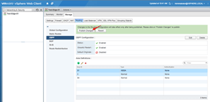
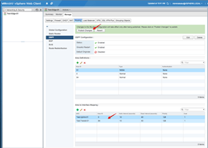
To ensure the Area ID‘s are mapped to the correct Interface‘s we need to specify the mappings.
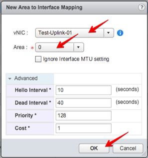
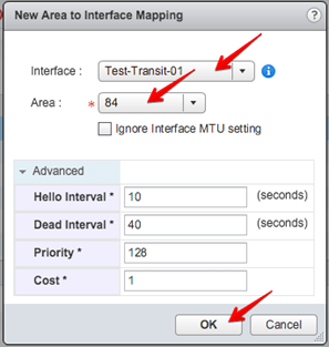
Click the Green + sign in the Area to Interface Mapping.

Select for:
vNIC : Test-Uplink-01
Area : 0
Leave the rest as defaults
Click OK.
Note: Here we are mapping the Uplink of the Edge Gateway to Area 0. Thus enabling up-stream route advertising.
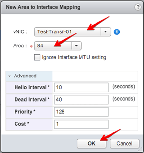
Select for:
vNIC : Test-Transit-01
Area : 84
Leave the rest as defaults
Click OK.
Note: Here we are mapping the Transit of the Edge Gateway to Area 84. Thus enabling down-stream route advertising to our private Area Definition.
Confirm settings and Click Publish Changes.
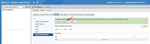
We now need to inform OSPF to do proper Route Re-Distribution.
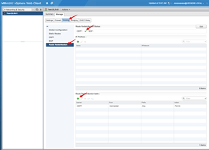
Click Manage, Routing and then Route Redistribution.
Click the Green + sign in the Route Redistribution table.

Ensure the Learner Protocol is fedault at OSPF.
Click the tick boxes next to:
Static routes
Connected
Click OK.

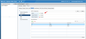
Click the Edit button in the Route Redistribution Status.

Click the tick box next to OSPF.
Click OK.
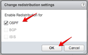
Click Publish Changes.
In the Edge Router console type:
show ip route
The current routing table is shown.
NO OSPF routes will show yet as we need to configure our DLR as well.
This is next.
Click NSX Edge in the Left Menu.
Then Double Click the DLR:
Test-DLR-01
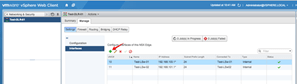
Click Manage, Settings and then Interfaces.
There are only two interfaces shown:
Test-LSw-01
Test-LSw-02
We are now going to add the Transit
Interface to connect to the Edge Gateway.
Click the Green + sign.
Type a Name in the field:
Name : Test-Transit-01
Type : Uplink
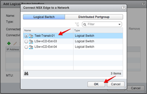
Select the Select button.
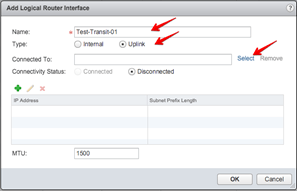
Select the Test-Transit-01 Logical Switch
Click OK.
Click the Green + sign to add an IP.
Click the Green + sign to add an IP.
192.168.200.2
Click OK.
Note: Remember that the 192.168.200.1 is the Internal Interface on our Edge Router Gateway.

Verify configuration.
Click OK.
All three interfaces are shown.

Select Manage, Routing and Global Configuration.
In the Default Gateway, Click Edit.

Select the following:
Interface : Test-Transit-01
Gateway IP : 192.168.200.1
Click OK.
Note: When we did the setup of the DLR, we did NOT configure the default route. This was intentional, as we are doing it here now. The default gateway for the DLR will be 192.168.200.1 via the Test-Transit-01 Interface.
Click Publish Changes.
Next is to setup the Dynamic Routing Configuration.
The DLR needs a Router ID, similar to the Edge Gateway, is also need to be unique for the OSPF tables to funtion properly.
Click Manage, Routing and Global
Configuration.
Click on Edit button in the Dynamic Routing Configuration.
Select the following:
Router ID : Test-Transit-01 – 192.168.200.2
Click OK.
Check changes and Click on Publish Changes.

Now we can configure OSPF.
Click Routing, OSPF and then the Edit button.

Click in the tick box to Enable OSPF.
Complete the following:
Protocol Address : 192.168.200.3
Forwarding Address : 192.168.200.2
Leave the Enable Graceful Restart enabled.
Leave the Enable Default Originate un-ticked.
Click OK.
Note:
Protocol Address – This needs to be an IP address that exist in the Transit network subnet. In our case the 192.168.200.0/24 range. It is the IP address that will be assigned to the Helper Router VM to do the OSPF peering. To the Edge Router Gateway.
Forwarding Address – This is the address of the DLR in the Transit network, to where the dynamic OSPF routes will be forwarded to/from.

We also need to set the Area Definitions for the DRL router, the same we did for the Edge Router Gateway.
Click on the Green + sign to add an Area Definition.

Here we add the same private Area Definition we used on the Edge IE:
Area ID: 84
Leave the rest as default.
Click OK.
We have added the Area Definition, now we need to do the Area Mapping to the Interface.
Click on the Green + sign in the Area to Interface Mapping.

Select the following:
Interface : Test-Transit-01
Area : 84
Leave the rest as default.
Click OK.
Click Publish Changes.

After setting the Area Definitions, we need to instruct OSPF how to Redistribute the routes.
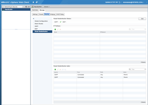
Click Routing, Route Redistribution.
Check that OSPF has a Green tick.
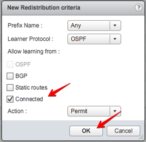
Click the Green + sign in the Route Redistribution table.
Select the following:
Learner Protocal : OSPF (default)
Tick the box for Connected.
Click OK.
Click Publish Changes.
That completes the configuration.
Testing/checking the configuration.
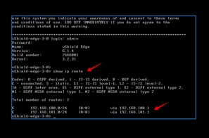
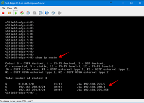
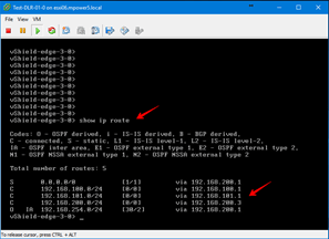
Open the Edge Router console.
Type the following:
show ip route
You should now see two additional routes, as advertised via OSPF. They are marked with the following:
O : OSPF Derived
E2 : OSPF external type 1

Open the DLR console
Type the following:
show ip route
You should now see an OSPF route added of the following:
O : OSPF Derived
IA : OSPF inter area
Doing an end to end test from TestVM01 to the external Internet Router will yield this result. Why?
Simply, remember we selected Auto Rule generation and set the Default Rule to DENY, when we created the Edge device. To fix this we need to either Disable the Firewall on the Edge (NOT reccomended) or simply create a rule to allow the traffic.
Click the NSX Edges, Double Click the Test-Edge-01.
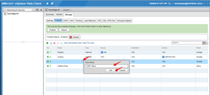
Click Manage, Firewall.
Click on the Green +
sign to add a new rule.
Give the rule Name:
Name : ICMP Allow
Click OK.
In the Service column select:
Service : ICMP Echo
Click OK.
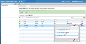
Click Publish Changes.
Doing an end to end test from TestVM01 to the external Internet Router will yield this result. Success!

Testing from TestWin01 to the other VM’s are still working.
- Comment
- Reblog
-
Subscribe
Subscribed
Already have a WordPress.com account? Log in now.
